Daniel Jonas 1978
Duchess
Until Daniel Jonas taxied
up to our hanger here in Santa Maria We had never done a complete
installation with Custom Panels, Custom Lights, and all the rest of the stuff
Avionics West is noted for on a Beech Duchess
before.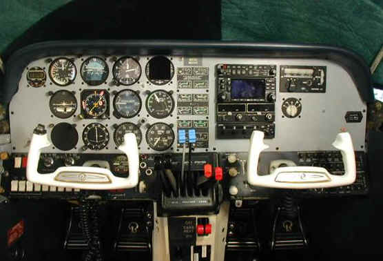 Usually its the Cessna 182s and the 210s
that get our treatment. So when Daniel
agreed to the upgrade I just had to add it to our feature projects. I have to admit that a Duchess is one of the
most enjoyable twins to fly in because of its excellent visibility. From the front seat you cant see the nose of
the aircraft because of its downward slope.
Looking out the huge front window all you see is the world coming at
you. Anyway------ Back to the
project.
Usually its the Cessna 182s and the 210s
that get our treatment. So when Daniel
agreed to the upgrade I just had to add it to our feature projects. I have to admit that a Duchess is one of the
most enjoyable twins to fly in because of its excellent visibility. From the front seat you cant see the nose of
the aircraft because of its downward slope.
Looking out the huge front window all you see is the world coming at
you. Anyway------ Back to the
project.
When the plane arrived it
was pretty well equipped with avionics:
Garmin 340 Audio panel, GNS 430, KX 155, and a Garmin GTX 320. Not too shabby really. What more could one want in a light twin like
this. Well, Daniel wanted a lot more. How about getting rid of the KX 155 and
adding a second 430 for back up, and, how about a Ryan 9900B TCAD so youll know
where everyone is up there, and, maybe a
GDL 69 Datalink Receiver so you wont have the need to consult with the flight
service station for your weather and TFRs before you leave, and, as long as we have a lot of data to display to
the pilot, we might as well just put it
all together on an MX 20 I/O with Chartview Great! Now we dont need any
sectionals or airport directories. I
tried to talk Daniel into getting the GDL 69A with XM radio instead of the
Vanilla model but he insisted on not having anything installed that would
distract him from his duties of flying the airplane??????????? Maybe I should have suggested an
autopilot!
In order to make the new
radios more useable and make the MX 20 more viewable to the pilot it would be
necessary to move them to the left. The
only way that was going to happen was to relocate the huge engine cluster over
to the right side of the panel and put the left hand radio stack in its
place. Now if we move the Century III
autopilot and Radio coupler over to the left side of the instrument panel where
the pilot can control it with his left hand we open up a large enough area to
install a second radio stack with the MX 20 being at the top and the transponder
below. By the way, Daniel also wanted
to replace the GTX 320 transponder with a Garmin GTX 327. Good looks and no
knobs! Actually I find it better for me
to have one with knobs. Having a knob gives me something to hang on to when Im
bouncing around up there in my Cessna 150.
Well now its time for the fun
part of the job, tear apart time! You are looking at is the original
aircraft instrument panel that was modified to accept the last configuration of
radios and an overlay panel was fabricated to match the instrument holes in this
original. Someone with a file and a lot
of time on their hands had to duplicate the instrument holes in the overlay
panel so they would fit just right to mount the instruments correctly. As it was, the instruments were mounted to
two thicknesses of .080 of material.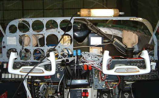 This caused the instruments to
be set back so far that they werent even flush with the panel front. We will not do that with our new panel even
though the instruments are not to be moved from their present locations. The plan here is to cut out the left side of
the panel like the right side is leaving enough material around the perimeter to
attach our new one. This will bring the
panel thickness back to the original dimension.
Working in an avionics shop and doing these installations is like being a
detective in forensics. As you dig down
into the menagerie of wires, connectors and butt splices a story unfolds telling
the airplanes history of avionics and electrical modifications. It is especially revealing when there are
layers of major upgrades still in the airplane.
Anytime a major avionics upgrade has been done without taking out all of
the old equipments associated wiring, switches, mounting racks etc, you end up with
layers of installations and a much degraded wiring system as a whole. Its like having a
mess on top of a mess. It finally
becomes impossible to give the customer a quality product unless the whole kit
and caboodle is taken out and redone. I
have had many disgruntled customers with airplanes I have refused to work on
because of this condition. Sorry! The
wiring in the Duchess was actually not too bad and since the only piece of
equipment that was being removed was the KX 155 most of the wiring would
stay. The power, Ground, and audio wires
for the old KX 155 would be connected to the new GNS 430 through an interface
connector making it a plug-and-play ordeal.
All remaining interfaces in the aircraft wiring will be made into an 29 pin circular connector. The mate to it will be on the new harness
assembly for the MX20, transponder and data lines which will be fabricated on
the wiring bench along with the mounting racks for each radio. The idea is to do as much work on the wiring
before it goes into the airplane as you can and when it does, make it as easy as
possible to connect to all of the interfaces.
Some places where you must reach in general aviation aircraft are
extremely hard to reach. There are many tricks of the trade that are only
learned through experience. The ideal
avionics installer is 3 feet tall, ambidextrous, and can stand on their head for
extended periods of time!
This caused the instruments to
be set back so far that they werent even flush with the panel front. We will not do that with our new panel even
though the instruments are not to be moved from their present locations. The plan here is to cut out the left side of
the panel like the right side is leaving enough material around the perimeter to
attach our new one. This will bring the
panel thickness back to the original dimension.
Working in an avionics shop and doing these installations is like being a
detective in forensics. As you dig down
into the menagerie of wires, connectors and butt splices a story unfolds telling
the airplanes history of avionics and electrical modifications. It is especially revealing when there are
layers of major upgrades still in the airplane.
Anytime a major avionics upgrade has been done without taking out all of
the old equipments associated wiring, switches, mounting racks etc, you end up with
layers of installations and a much degraded wiring system as a whole. Its like having a
mess on top of a mess. It finally
becomes impossible to give the customer a quality product unless the whole kit
and caboodle is taken out and redone. I
have had many disgruntled customers with airplanes I have refused to work on
because of this condition. Sorry! The
wiring in the Duchess was actually not too bad and since the only piece of
equipment that was being removed was the KX 155 most of the wiring would
stay. The power, Ground, and audio wires
for the old KX 155 would be connected to the new GNS 430 through an interface
connector making it a plug-and-play ordeal.
All remaining interfaces in the aircraft wiring will be made into an 29 pin circular connector. The mate to it will be on the new harness
assembly for the MX20, transponder and data lines which will be fabricated on
the wiring bench along with the mounting racks for each radio. The idea is to do as much work on the wiring
before it goes into the airplane as you can and when it does, make it as easy as
possible to connect to all of the interfaces.
Some places where you must reach in general aviation aircraft are
extremely hard to reach. There are many tricks of the trade that are only
learned through experience. The ideal
avionics installer is 3 feet tall, ambidextrous, and can stand on their head for
extended periods of time!
The Antennas are installed.
With the addition of the second
GPS, the Ryan TCAD and the GDL 69 Weather Datalink Receiver we ended up with
quite an array of antennas on the roof.
We always try to arrange them is some king
of order so as not to create a just-stick-it-anywhere look
like so many planes have nowadays. The
top mounted Ryan TCAD antenna shown above is similar to a transponder blade
antenna as it should since it receives transponder reply signals from the
airplanes around you. The ideal location
to mount the top Ryan TCAD antenna is at the highest place on the fuselage so
that is has an unobstructed view of the forward horizon. This will allow for the systems best
performance in looking forward for incoming traffic threats. In the Ryan Traffic system the top antenna is
responsible for sensing the targets forward and aft for Multifunction display
purposes.
The
bottom antennas are responsible for sensing the left and right positions of
the traffic. The TCAD processor takes
the signals from each antenna and is able to determine exactly what bearing the
traffic is positioned with respect to your airplanes heading.. The processor now calculates the vertical
separation between your airplane and other aircraft by comparing the mode C
transponder signal received from the other airplane with the
your onboard altitude encoder which is hardwired to the processor. So far we have bearing and
 Vertical separation but what about distance? How far away is it? This is the grey area of the system and I
havent had a straight answer from any of the Ryan engineers about how this
works. Since the Ryan 0900B TCAD is a
passive system, it only receives.
Therefore the only way it can determine how far away an RF signal was
originated, it would have to assume that the signal power was at a certain level
at the time of transmission. Now, us
Avionics types know that all transponder out there dont transmit at the same
power level, in fact,
there can be as much as 200 to 250 watts peak difference between
them! Maybe we can get one of the Ryan
engineers to write and explain it a little better.
Vertical separation but what about distance? How far away is it? This is the grey area of the system and I
havent had a straight answer from any of the Ryan engineers about how this
works. Since the Ryan 0900B TCAD is a
passive system, it only receives.
Therefore the only way it can determine how far away an RF signal was
originated, it would have to assume that the signal power was at a certain level
at the time of transmission. Now, us
Avionics types know that all transponder out there dont transmit at the same
power level, in fact,
there can be as much as 200 to 250 watts peak difference between
them! Maybe we can get one of the Ryan
engineers to write and explain it a little better.
Coax Lengths are Important
Each one of the
antennas is connected to the processor with two lengths of Coax. Four in all. Each one of these lengths of coax must have
a 3db signal attenuation at 1000 Mhz for the correct
loading on the antennas and amplifiers of the system. Any more or less than that will cause the
system to be degraded. WE have found
that 17 ft of RG 400 works just fine for just about any GA aircraft
installation. If the distance between
the processor is less than 17 ft then coil the excess coax and stow it neatly by
the processor. Do not use RG 58 for
short runs. RG 58 is inferior to these installations and Remember
when coiling up coax or routing it in general do not exceed its minimum bend radius which
is 10 time the diameter! Im starting to
sound like an aerospace quality inspector now.
Sorry!
Installations like these takes good planning, innovativeness, and
absolute attention to details. There is
probably not another profession which deals in such complexity and tedious
tasks. It usually takes 3 to 4 years to
train an Avionics tech to be proficient at all of these things. The reward of doing a good installation is the feeling you get when you turn on
power for the first time after the install and everything starts up and works
like its suppose to. As far as Avionics
is concerned, there is nothing worse than rework. By Steve Walker, Owner of
Avionics West, Inc. For more information Drop Steve a Note.


